6: The Recoil Escapements
Once you have the Graham escapement drawings, drawing the recoil escapements is easier because the images could be superimposed for reference.
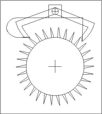 |
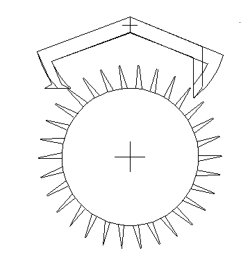
With the recoil escapements, there is no need to adjust for lock, only drop. This really simplifies the issue. Just create some inside and outside drop, and make sure that the angle FeFi is 45°. Since no adjustment is made for lock, use the ideal Graham drawing for reference. Shorten the entry pallet slightly and move the exit pallet slightly outwards, parallel to the impulse face of the Graham exit pallet. Notice that the escape wheel has been changed. This is the result, once the Graham is removed:
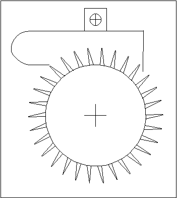 |
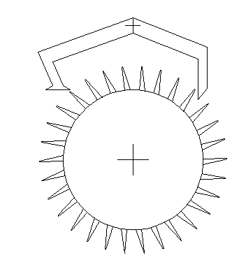
Now for another recoil pallet, this time superimposing one recoil pallet over another:
|
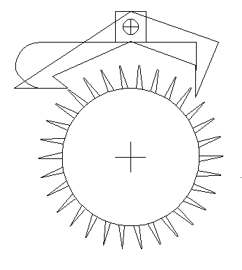
This design is similar to one I saw recently in an antique British grandfather clock:
|
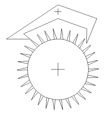
The following is the most important fact about recoil escapements: the angle FeFi
must be 45°, regardless of the angle FeFp. This is because of recoil action. If the
efficiency were 50%, or 1/2, moving forwards, then the deceleration of recoil would have
twice the magnitude of Fe (in the opposite direction). Some power is "stored" in the
recoil action because the escape wheel moves back a little, as if it were winding the
clock. However, the power stored is only 50% of Fe, so we have a very significant power
loss, even under the best conditions.
If the impulse face's angle were 15°, the efficiency would be 25%, or 1/4. The
deceleration of recoil would be four times as large as Fe in the opposite direction. Having
the impulse face's angle at 15° causes two problems: (1) more efficiency is lost moving
forwards because of the incorrect angle, and (2) much more power is lost in recoil (going
backwards).
This example demonstrates how important the impulse face's angle is in a recoil
escapement. The angle FeFi must be 45° to minimize power losses in recoil. Therefore,
the angle FeFp should be 90° in order to maximize efficiency moving forwards. How
many recoil escapements have you seen that had the correct angles?
Table of Contents
Escapements in Motion
Clock Repair Main Page
Links Page